John L. Obrien Building
General Project Info
- Location: Olympia, WA
- When: 2007 - 2011
- Company: Forma Construction
- Footprint: 100,700 sq.ft.
- My Role: Laborer
History of the building
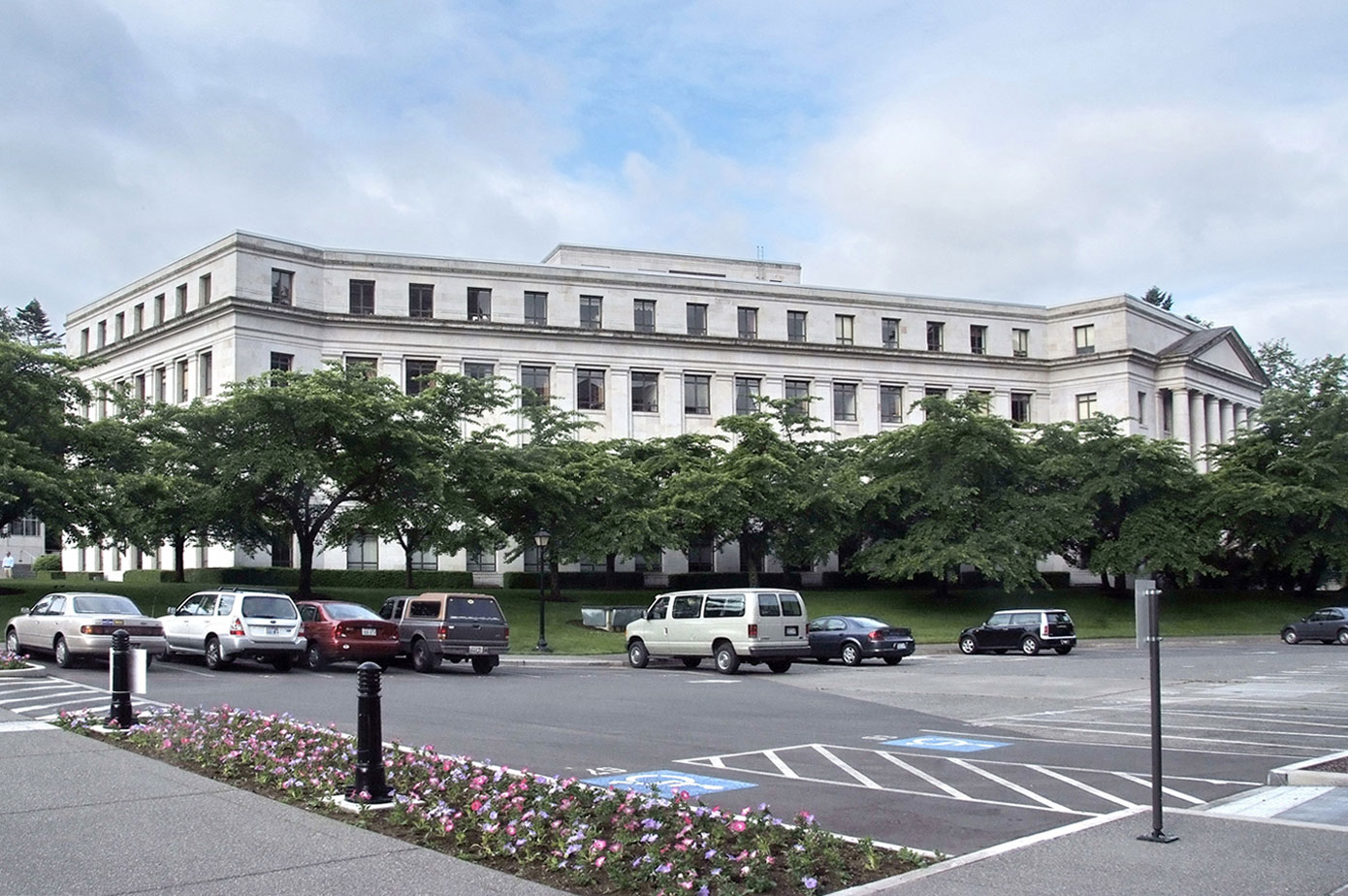
The John L. O’Brien Building is one of six government buildings envisioned in the 1911 Capitol Master Plan. Construction began in 1938 and was completed in 1940. While built with reinforced concrete, the exterior walls feature broad expanses of unadorned sandstone. Pediment porticoes accent the north and west facades helping to align with the architectural design of the Capitol Group. The building was added to the National Register of Historic Places in June of 1979. It is the architectural companion to the John A. Cherberg Building, with a public plaza located between them and the Legislative Building, following the original Capitol Campus Plan by Wilder and White.
Designed by architect Joseph Wohleb and originally called the “Transportation Building,” this 100,700 square foot building is four-stories with a full daylight basement. It exhibits a bold Neo-Classical Revival composition with strong interior Art Deco design influences. The building was constructed with funding from the federal Project Works Administration and originally housed the state Highways Department and other agencies. In 1962, interiors were remodeled, occupancy changed and it was renamed the “Public Health Building.” It was significantly remodeled a second time in 1970, to serve as offices for the House of Representatives. It was renamed in 1989 in honor of John L. O’Brien, speaker of the House from 1955 to 1963, longer than anyone else in state history.
A nearly $50 million rehabilitation of the building was completed in 2014. The multi-phase project overhauled the mechanical, electrical and plumbing systems, corrected life-safety code deficiencies, strengthened seismic resistance and realigned offices to improve space use of the upper three floors.
The upgrades and improvements were discreetly woven into the fabric of the 73-year-old building in ways that avoided or minimized impacts to historic walls or finishes.
🧩 Construction Project Features
- Over 4 phases, we added 14” concrete shear-walls from the basement to the roof for increased seismic resilience.
- The shear-walls bear upon various mass-foundation placements below the basement floor. The new foundations were capped with a monolithic CDF (controlled-density-fill) pour, filling the entire length of the building, supporting the basement slab.
- Most portions of the floor-to-ceiling marble interior finishes were temporarily removed and stored off-site at the state’s curator’s ‘vaults’ and re-installed, post construction.
- The exterior sandstone veneer was sourced out-of-state and no longer available so every piece of the exterior was treated as price-less and could not be removed, damaged, or even stained.
- At the exterior south side of the building, we excavated more than half the entire length of the building by 14 feet deep to build a new underground main electrical room, backup generator room, and a mechanical room, all underground. The new electrical switch-gear, cummins deisel engine generator and hvac air-handling units all had to be installed prior to the 14” thick ‘roof’ deck could be poured because of their size. (Part of the ‘roof’ was covered with topsoil and is currently a garden area and the other portion is now parking area.)
- The air-handling unit was so large that it came with full-size walk-through doors to get inside to change out the filters.
- The back-up generator was a custom-made 20-cylinder diesel engine that sits more than 10 feet tall and over 20 feet long.
💡 Technologies and Skills I used
- Elevation control
- Reading plans
- Reading shop-drawings
- Rigging and hoisting
- Electric core-drilling and pneumatic rock-drilling
- Epoxy placement
- Form-building
- Planning and schedule coordination
Photos
A temporary ramp to the basement
 There was a lot of work on the first phase, which included the basement and the roof, which was temporary in nature and got completely removed in later phases. This concrete ramp was installed to create a stable path to remove hundreds of yards of soil from underneath the basement floor with machinery.
Dig out the foundations under the basement
 The protective roll cage on this machine had to be removed in order for it to fit (and be useful) inside the basement. Bulk excavation was performed this way.
Expose the existing foundations…
 But once the machine ‘hit’ the existing concrete, the rest had to be excavated by hand, and neatly (flat bottom and sides) because this would all eventually get filled with concrete.
…By hand at the end…
 I wish I had photos showing the rebar we installed in these foundations. Essentially, all of the open space you see in these photos were filled with ‘hoops’ and ‘dowels’ which would transform the building’s foundation from separate individual footings like you see in the image, to giant, monolithic foundations spanning large portions of the building.
Build the shear-walls with lots of rebar
 There was also alot of rebar in the shear walls. Also, all of these vertical walls inside the building were placed using ‘shot-crete’ method where we just form up one face (and the ends) of the wall and they ‘shoot’ the concrete against it and ‘strike’ it (level it off) with long screeds. If you look closely, all of the rebar continues up through the ceiling…
Lots of drilling over-head…
 Yeah, there was a lot of drilling over-head. Some of it was drilling horizontally into the purlins and some was drilling up to the next level to identify where the extents of the wall was going to be in the next phase. There were a few times when we had to build temprary ‘boxes’ on the level above to cover up the ends of the rebar that were protruding through the floor from below in areas of the building that were still occupied.
Lots of drilling outside as well
 Like the inside of the building, we were attaching to the oustide of the foundation as well. I remember drilling two vertical holes and two horizontal holes, each about 16” deep, spaced about 6” apart down the whole length of this excavation. I can’t remember if it took a week or three weeks but it seemed like it took forever.
Shoring, waterproofing and new footing forms
 Here you can see the exterior waterproofing wrap on the shoring walls and the foundation forms getting installed.
Waterproofing complete and foundations are placed
 Then, once the footings were poured, they added another waterproofing membrane onto the shoring.
Columns, walls and slab
 Here you see the exterior walls and interior columns are placed. Notice how the columns are not centered in the room? That’s because between the columns and the building is where the new air-handler unit, back-up generator and electrical switchgear will be placed. That’s how big they are! The left side of the colums is a corridor to get to the three different rooms.
False-forms and interior walls
 Here you see some of the formwork for the interior walls and the false-work for supporting the new beams that will hold up the ‘roof’ of the new sub-terranean mechanical room. We poured these beams to top off the columns and then installed the equipment with a crane before we built the deck; there was no other way to do it.
Top deck in place with waterproofing membrane
 Here you see the end result of the structure. It’s a 14” thick concrete slab with waterproofing membrane, enclosing all the new equipment below. Part of this new room was covered with topsoil and became a landscaped area but a good majority of became paved parking at the back of the building.
After some backfill and paving, it’s ready to use, and use it, we did!
 Here you see a truck, scaffolding a dumpster and a lift, all mostly above the new mechanical room.
The Scaffolding stream-lined the demo crew’s ability to purge the rest of the floors

John L. O’Brien Floor to ceiling marble at the lobby

🌐 More Info
👉 Washington State Department of Enterprise Services: John L. O’brien Building
👉 Forma Construction Company Construction Video
🎯 Objective / Learnings
- Phased and temporary construction
- Extensive exposure to reading reinforcing shop drawings and structural drawings
- Advanced construction methods including:
- shot-crete
- false-work
- shoring
- under-ground fuel storage
- elevated work platforms and multi-story scaffolding
- Construction in occupied / partially-occupied spaces